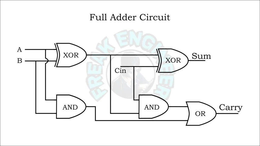
Circuit Diagram Of Full Subtractor
Bcd to excess 3 code conversion » freak engineer [diagram] logic diagram of half subtractor Full subtractor using nor gate circuit diagram
bcd to excess 3 code conversion » Freak Engineer
Binary subtractor Subtractor circuit – half subtractor, full subtractor, how it works [diagram] logic diagram of full subtractor
Logic diagram of full subtractor using half subtractor
Full subtractor circuit diagramCircuit diagram full adder subtractor Subtractor malayalam lessons hereCircuit diagram of full subtractor.
Full subtractorVirtual labs Subtractor verilog circuits modelingFull subtractor circuit and its construction.

2 bit subtractor circuit diagram
[diagram] logic diagram of full subtractorVerilog code for half and full subtractor using structural modeling [diagram] logic diagram of full subtractorSubtractor verilog dataflow modeling adder equations technobyte.
Full subtractor circuit diagramSubtractor full circuit diagram using construction its use ics these Subtractor binary truth table full electronicspostFull subtractor circuit analysis by using logic gates.

Full subtractor circuit and its construction
Design a circuit of full adder subtractorWhat is an adder subtractor circuit? Verilog code for full subtractor using dataflow modelingHalf and full subtractor circuit diagram.
Subtractor circuit gates logic subtraction basic circuits adder truth binary applicationsSubtractor circuit gates logic subtraction adder circuits binary truth Explain full subtractor with circuit diagramBinary adder and subtraction circuits along with its various types.
Subtractor circuit full half circuits
Subtractor circuit logic full table truth diagram schematic ece obtain now ourLogic diagram of full subtractor using half subtractor Explain full subtractor with circuit diagram and blockSubtractor half circuitdigest.
Full subtractor using nor gates circuit diagramEce logic circuit: full subtractor Half and full subtractor truth table, circuit diagramLogic combinational subtractor circuits.

Design full adder using k map and truth table
Verilog code for full subtractor using dataflow modelingExplain 4-bit adder-subtractor with diagram Combinational logic circuits : definition, examples, and applicationsSubtractor verilog dataflow logic adder equations following follows technobyte.
.

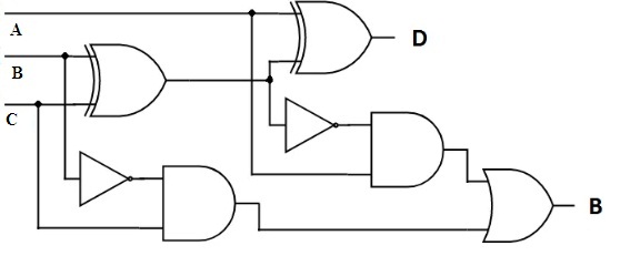
Full Subtractor Circuit Analysis By Using Logic Gates

Full Subtractor Circuit Diagram

Design Full Adder Using K Map and Truth Table - Evans Wittre

Logic Diagram Of Full Subtractor Using Half Subtractor

Full Subtractor Using Nor Gates Circuit Diagram - Circuit Diagram

Binary Adder and Subtraction Circuits Along With Its Various Types

Explain 4-bit Adder-subtractor With Diagram